
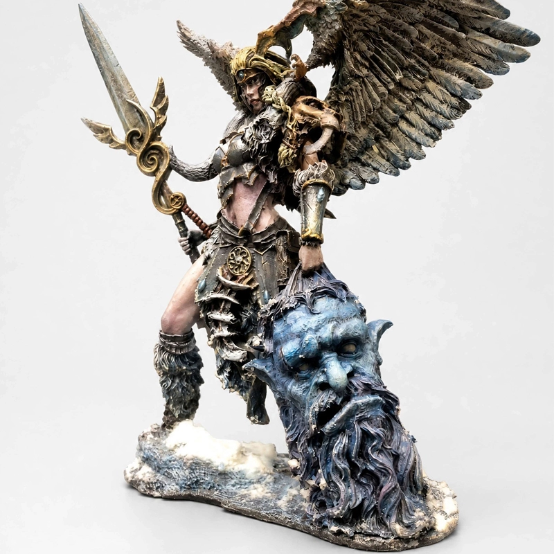
The short answer: a production-ready tech pack contains six things: orthographic views, dimensional callouts, material and finish specification, colour references, decoration and print areas, and functional plus safety requirements. Mood boards, single JPEGs and verbal briefs are inputs to a conversation, not inputs to production. Every gap in the pack is filled by the factory's interpretation, and interpretations must be corrected later through revision rounds and, sometimes, after tooling. A complete tech pack is the cheapest schedule insurance available — it costs a few days at the start and saves weeks downstream.
There is a consistent pattern in projects that run late and over budget: the factory was asked to begin sculpting from an incomplete brief, and every subsequent stage inherited an assumption that nobody wrote down. The assumption usually surfaces at the sculpt review, where the buyer says "that is not what I meant" — and by then the sculpt has to be rebuilt before tooling can begin.
This article sets out what a tech pack is, exactly what belongs in each section, what is not sufficient, how to run a readiness review before handoff, and how the quality of the pack propagates through the rest of the programme.
In this article
- What a tech pack is for
- The six sections that must be present
- Orthographic views and why they matter
- Dimensions and tolerances
- Materials, finishes and colour
- Decoration and print areas
- Function and safety requirements
- What is not sufficient
- How a thin pack costs you money
- The handoff readiness review
- Format and file handling
- Handoff checklist
What a tech pack is for
A tech pack is the document that lets a factory build your product without asking you questions. That is the whole test. If the pack leaves an ambiguity, the factory will resolve it — and it will resolve it in the direction that is easiest to manufacture, which is not always the direction you intended.
It is a specification, not a description
The distinction is worth holding onto, because buyers routinely produce documents that describe a product without specifying it. A description says "a stylised figure with a flowing cape." A specification says which surfaces are visible from which angle, how thick the cape is, where it attaches, and what tolerance the attachment must hold. The first cannot be built; the second can.
| Purpose | What it prevents |
|---|---|
| Defines the product unambiguously | Factory interpretation becoming your specification |
| Enables accurate quoting | Cost surprises after tooling |
| Anchors the approval gates | Arguments about what was agreed |
| Supports consistent repeats | Run-to-run drift between orders |
| Documents change history | Losing track of which version is current |
A useful framing: the tech pack is a contract in technical form. The commercial contract says what you pay and when; the tech pack says what you receive.
The cost asymmetry it exists to exploit
There is a stark asymmetry in custom manufacturing: the cost of resolving an ambiguity rises steeply the later it is resolved. The same question — is this surface meant to be flat or curved? — costs a sentence in the pack, an email at the sculpt stage, a revision round at the structural stage, and a tool modification after T1. The tech pack exists to force those questions to the earliest and cheapest point.
| When the ambiguity is resolved | Relative cost | Effect on schedule |
|---|---|---|
| During pack preparation | Negligible | None |
| At sculpt review | Low | One revision round |
| At structural review | Moderate | Rework before tooling |
| After tooling | High | Tool modification, schedule slip |
| After mass production starts | Very high | Scrap, re-tooling, missed launch |
The asymmetry is not intuitive, because the ambiguity itself costs nothing at the moment it is created. It costs nothing to write a brief with an unstated wall thickness. The cost appears weeks later, attributed to something else.
What the factory does with a complete pack
Understanding how the pack is used inside the factory clarifies why each section matters. A complete pack flows through four internal functions, and each one consumes a different part of it.
| Function | What it reads from the pack | Failure mode if missing |
|---|---|---|
| Quoting | Material, size, part count, decoration steps | Quote is revised after selection |
| Sculpting and engineering | Views, dimensions, structural requirements | Design reworked before tooling |
| Tooling | Geometry, tolerances, surface finish | Tool cut to the wrong specification |
| Quality and compliance | Colour standard, function, age and market | Testing failure discovered late |
The quoting function is the one buyers most often overlook. A thin pack does not prevent a quote; it produces a quote built on assumptions, and those assumptions become visible only when the assumptions are corrected — usually as a price increase at a moment when you have limited room to re-tender.
The six sections that must be present
A complete pack covers six areas. Each one answers a class of question the factory would otherwise have to guess at.
| # | Section | The question it answers |
|---|---|---|
| 1 | Orthographic views | What is the shape, from every side? |
| 2 | Dimensional callouts | How big is every feature, and how precise? |
| 3 | Material and finish | What is it made of, and how does it feel? |
| 4 | Colour references | Exactly which colours, to what standard? |
| 5 | Decoration and print | What is painted or printed, and where? |
| 6 | Function and safety | What must it do, and what must it pass? |
Packs that omit any one of these six tend to fail at a predictable point. Missing views fail at sculpt approval. Missing dimensions fail at structural review. Missing material specification fails at quoting. Missing colour references fail at the deco sample. Missing decoration layout fails at tool trial. Missing function and safety requirements fail at compliance testing, which is the most expensive place to fail.
Why the six are interdependent
The six sections are not independent chapters; they constrain each other. A change of material changes achievable wall thickness, which changes the structural design, which may change the split lines, which affects decoration placement. This is why a pack assembled section by section without cross-checking tends to contain internal contradictions that only surface during engineering.
| If this changes | These are affected |
|---|---|
| Base material | Wall thickness, finish, weight, compliance |
| Overall dimensions | Part splitting, packaging, shipping volumes |
| Finish | Decoration method, tool surface, defect visibility |
| Decoration layout | Part orientation, registration, protected areas |
| Function requirement | Structure, joints, tolerance, material |
| Age grading | Small parts, stability, chemical limits |
A worked example of the interdependence
Consider a small articulated figure with a printed chest emblem. The material choice determines whether the chest surface can be moulded flat enough for clear printing; the wall thickness determines whether that flat area will sink; the finish determines whether minor sink marks will be visible; and the age grading determines whether the emblem paint must meet additional chemical limits. Four sections, one shared decision — and if the pack states them independently, the factory will make the four decisions separately and the conflict will appear at the tool trial.
The practical remedy is a cross-check pass: after the pack is assembled, read it once looking only for contradictions between sections rather than for completeness within them.
Orthographic views and why they matter
Orthographic views — front, back, left, right, top, bottom — are the backbone of the pack. A perspective render or a hero illustration communicates mood; it does not communicate geometry, and geometry is what gets tooled.
- Six views minimum — every surface that will be moulded must be visible in at least one view.
- Consistent scale — all views at the same scale so proportions can be checked against each other.
- Aligned projection — front and side views aligned on shared centrelines so features can be cross-referenced.
- Section views where hidden — cutaways for internal features, sockets, joints and assembly interfaces.
- Exploded view for multi-part items — showing how parts separate and reassemble.
If you have only a sculpt model and no drawn views, the sculpt itself often serves as the geometry source — but the pack should still state the intended overall dimensions so that the sculpt can be checked against them rather than accepted uncritically.
Why perspective renders mislead
A perspective render is designed to look convincing, which is precisely what makes it unsuitable as a geometry source. Perspective foreshortens, exaggerates near features and hides far ones. A figure that looks well-proportioned in a three-quarter hero render can be visibly wrong when seen from the side, and the side view is the one the customer will eventually see on a shelf.
- Foreshortening — depth is compressed or exaggerated depending on the camera distance.
- Hidden surfaces — the entire back and underside are unrepresented.
- Lighting cues — shading suggests form that the geometry may not actually have.
- No scale — a render can be printed at any size, so it carries no dimension.
- Composition bias — the framing flatters one angle at the expense of the others.
The six views and what each one settles
| View | What it settles | Common omission |
|---|---|---|
| Front | Symmetry, overall width, face and chest detail | Centreline omitted |
| Back | Rear detail, closure, attachment points | Left entirely undesigned |
| Left and right | Depth, profile, limb position | Only one side supplied |
| Top | Head shape, shoulder width, flat areas | Ignored on figures |
| Bottom | Base, feet, mounting interface | Base geometry undefined |
| Section | Internal structure, wall thickness | Left to the factory |
The back view is the most frequently omitted and the most consequential. A figure designed entirely from the front will have a back invented by the sculpting team, and that invention will be plausible rather than intended.
| View supplied | What it communicates | What it cannot |
|---|---|---|
| Hero render | Mood, lighting, colour intent | Accurate geometry, hidden surfaces |
| Single front photo | Front silhouette only | Depth, back, internal structure |
| Concept sketch sheet | Design intent, proportions | Accurate dimensions |
| Six-view orthographic | Full geometry | Surface finish detail |
| Six-view plus sections | Geometry and internals | Nothing structural |
| Sculpt file plus drafted views | Everything geometric | Nothing geometric |
Dimensions and tolerances
Dimensions turn a shape into a manufacturable object. Two numbers matter for every critical feature: the target size and the acceptable variation around it.
- Overall dimensions — height, width, depth of the finished item, with the measurement reference stated.
- Critical feature dimensions — anything that must interface with another part, a base, a stand or a package.
- Tolerances — the permitted variation. State them for critical features rather than leaving the factory to apply its default.
- Wall thickness guidance — where the design is thin or thick, and whether that is intentional.
- Assembly clearances — the gaps that allow parts to fit without force.
How to state a tolerance without over-constraining
There is a real trade-off in tolerance specification. Tight tolerances cost money — they demand better tooling, slower cycles and more inspection. Loose tolerances risk fit problems at assembly. The error most buyers make is not tightness or looseness but uniformity: applying one tolerance to every feature instead of reserving precision for the features that need it.
- Tighten only what interfaces — features that mate with another part deserve precision; cosmetic surfaces often do not.
- State the reference — a dimension is meaningless without knowing what it is measured from.
- Distinguish nominal from critical — mark the features where variation actually matters.
- Ask what the default is — factories apply their own default tolerance if none is given, and it may be looser than you would choose.
- Check for stacking — several loose tolerances in a chain can combine into a fit failure.
Tolerance stacking deserves a specific mention because it is invisible on a drawing. Four parts each within their individual tolerance can still assemble badly if the tolerances all push the same direction — a situation no single dimension check will detect, and one that only appears at assembly, which is the expensive place to find it.
| Dimension type | Why it matters | Risk if unspecified |
|---|---|---|
| Overall size | Packaging, shipping, shelf fit | Product does not fit its own box |
| Interface points | Parts must mate | Assembly failure at production speed |
| Tolerance | Controls consistency | Batch-to-batch variation |
| Wall thickness | Strength, weight, sink marks | Warping or premature breakage |
| Clearances | Fit without force | Scrap rate at assembly |
Materials, finishes and colour
Material specification drives cost, weight, durability and compliance. Leaving it to the factory's default is how products end up heavier, softer or less durable than intended.
| Element | What to state | Why ambiguity is costly |
|---|---|---|
| Base material | Family and grade, or performance requirement | Substitution changes cost and feel |
| Finish | Gloss, matte, satin, texture | Visual identity drifts |
| Hardness or rigidity | Functional requirement | Product feels cheap or fails in use |
| Colour standard | Pantone or equivalent reference | Colour matching becomes subjective |
| Colour placement | Which part is which colour | Parts painted the wrong shade |
| Compliance requirement | Target market standards | Failure at the testing stage |
Colour deserves emphasis because it is the most commonly under-specified element. "Blue" is not a specification. A Pantone reference on a specified substrate is, and it gives you something objective to compare against when the deco sample arrives.
Specifying by performance rather than by grade
You do not always have to name a material grade. You can specify by performance instead, which leaves the factory room to select a suitable grade while still binding it to an outcome.
| Instead of naming | You can specify | Why it can be better |
|---|---|---|
| A specific polymer grade | Required rigidity, impact and finish | Allows cost-effective substitution |
| A particular finish process | The required surface appearance and durability | Keeps method open without losing outcome |
| An exact wall thickness | A minimum thickness and a weight limit | Respects manufacturing requirements |
| A named paint product | A colour standard plus adhesion requirement | Survives supply chain substitution |
Performance specification is a genuine technique rather than a shortcut, but it only works if the performance requirements are testable. "Durable" is not testable. "Survives a one-metre drop onto concrete without fracture" is. Where a requirement cannot be tested, it is better to name the material or process explicitly.
Compliance begins at the material line
Restricted substance requirements are met or failed at the material and decoration selection stage, not at inspection. A perfectly made product in a non-compliant substrate is a non-compliant product. The pack should therefore connect the material line to the target market, because the same product can be compliant in one market and not in another.
Why colour needs a physical reference
Colour is interpretive. Two people looking at the same blue on the same screen may see it differently, and a printed swatch differs from both. This is why the pack must reference a physical standard rather than describe a shade, and why the deco sample must be compared against that standard rather than against a memory of the render.
- Reference a standard — a named colour system with a specific code, not a colour name.
- State the substrate — the same colour reads differently on different materials and finishes.
- State the placement — which part, which surface, and which finish it sits on.
- Allow a tolerance — real production has a colour range; state what is acceptable.
- Compare physically — judge the deco sample against the physical standard, not on screen.
Decoration and print areas
Decoration is where product identity is concentrated, and where layout errors are most visible. The pack must show not only what the decoration looks like but exactly where it sits on the part.
Why placement is harder than artwork
Supplying artwork is straightforward; supplying its position is not. An emblem on a flat panel is easy to place. The same emblem wrapped across a curved shoulder is a different problem, because the artwork must be pre-distorted so that it appears correct once applied. If the pack shows the artwork flat beside the part rather than mapped onto it, the factory either guesses or applies it undistorted and the result looks wrong.
| Surface | Placement difficulty | What the pack must show |
|---|---|---|
| Flat panel | Low | Position and margin from edges |
| Single-curve | Moderate | Position plus distortion direction |
| Compound curve | High | Mapped artwork with distortion shown |
| Full wrap | High | Seam position and registration |
| Recessed area | Moderate | Depth and clearance for the tool |
- Deco placement — decorated views with the artwork positioned on the physical surface, not floating beside it.
- Wrap and curvature — how artwork behaves across a curved or compound surface.
- Registration — what the artwork must align to, and the tolerance on that alignment.
- Print method — tampo, pad, screen, transfer or in-mould, if the choice is constrained.
- Layering — the order of decoration where multiple colours or techniques overlap.
- Protected areas — surfaces that must stay clear for function or assembly.
Tooling for decoration
Decoration often needs its own tooling — a pad, a screen or a jig. That tooling depends on the placement you specify, which means a late change to decoration position can invalidate deco tooling even though the part tool is untouched. This is a cost that buyers frequently overlook when they treat decoration as a finishing detail rather than a specification.
| Underspecified | Symptom at sample stage |
|---|---|
| Placement | Artwork lands off-centre or rotated |
| Scale | Artwork too large for the flat area |
| Curvature handling | Distortion across the wrap |
| Registration reference | Eyes or logos misaligned with features |
| Layer order | One colour bleeding through another |
Function and safety requirements
This section is short in word count and disproportionately important in consequence. Anything the product must do, and anything it must pass, belongs here.
| Requirement class | Examples of what to state |
|---|---|
| Articulation | Which joints move, range of motion, retention strength |
| Assembly | Parts intended to separate, and the force required |
| Stability | Whether the item must stand unaided |
| Durability | Drop, torque or cycle requirements |
| Age grading | The age band the product is designed for |
| Compliance | Target market standards and testing scope |
| Chemical limits | Restricted substances applicable to the market |
Age grading and compliance are the two entries most often omitted by buyers who assume the factory will handle them. A factory will handle testing if instructed, but it cannot infer the target market, the age band or the intended use from a drawing. Those are commercial decisions, and the pack is where they are recorded.
Age grading is a design input, not a label
Age grading is frequently treated as a marking applied at the end, when in fact it constrains the design from the beginning. An item intended for a younger age band faces stricter requirements on small parts, openings, cords and material chemistry — constraints that may make certain design features unworkable.
| Age band consideration | Design implication |
|---|---|
| Small parts risk | Component size and retention may need redesign |
| Enclosed openings | Vent and gap dimensions may be constrained |
| Chemical limits | Material and decoration selection |
| Sharp edges | Fillet radii and moulded edge treatment |
| Stability | Base geometry and centre of gravity |
Getting the compliance decision right early
Compliance failures are the most expensive class of problem in a toy programme because they can invalidate an entire production run rather than a single part. The pack should identify the target market, the age band and the applicable standard, and the engineering review should confirm that the design is capable of meeting them before tooling is cut.
- Name the market — requirements differ by destination, and exports may face several at once.
- Name the age band — it determines which requirements apply.
- Identify the standard — so testing scope is known before it is booked.
- Flag fragile areas — features that may have difficulty meeting the requirement.
- Plan testing timing — testing slots need to be booked, not assumed available.
What is not sufficient
The following are commonly handed over in the belief that they constitute a brief. Each has a legitimate role, and none of them is a tech pack.
| Input | Legitimate use | Why it is not a tech pack |
|---|---|---|
| Mood board | Establishing direction and tone | Contains no geometry or specification |
| Single reference JPG | Illustrating a target look | One angle; no hidden surfaces or dimensions |
| Verbal brief | Framing the commercial goal | Not reproducible; invites interpretation |
| Competitor product photo | Benchmarking | Describes someone else's product, not yours |
| Concept sketch | Exploring proportions | Not dimensioned; decorative not definitive |
| AI-generated render | Visualisation | Often geometrically impossible to manufacture |
These inputs are valuable in a scoping conversation. The problem begins when they are treated as the handoff, because the factory then has to invent the missing specification — and inventing specification is engineering work that you are paying for either in money or in rework.
The specific danger of an AI-generated render
Generated imagery deserves its own note because it has become a common way to pitch a product internally, and it looks deceptively like a specification. A generated render can depict a form that satisfies no manufacturing constraint at all: impossible undercuts, floating parts, thicknesses that cannot be moulded, and details that dissolve on inspection. Presenting one as a technical input invites the factory either to refuse or to silently redesign, and the redesign will not match the image that convinced your stakeholders.
What a sculpt file does and does not replace
A digital sculpt is a substantial input and often enough to begin work — but it does not replace the pack. A sculpt defines surface geometry; it does not state material, finish, colour, decoration placement, function or compliance. Projects that hand over a sculpt and consider the brief complete typically reach the tool trial and discover that the decoration has no agreed position and the material has no agreed specification.
How a thin pack costs you money
The cost of an incomplete pack does not appear as a line item. It appears as extra rounds, extra weeks and occasionally extra tooling.
| Gap in pack | Where it appears | Likely consequence |
|---|---|---|
| Missing views | Sculpt review | Sculpt rebuilt before tooling |
| Missing dimensions | Structural review | Redesign of internal structure |
| Missing material spec | Quotation | Quote revised after selection |
| Missing colour refs | Deco sample | Repeated deco rounds |
| Missing deco layout | Tool trial | Artwork repositioned; deco re-run |
| Missing compliance scope | Testing | Late failure; possible re-tooling |
Why the cost is invisible when it is incurred
The reason thin packs persist is that creating one feels free. There is no invoice for an unstated wall thickness and no delay at the moment the brief is sent. The cost appears weeks later in a place that looks unrelated — a sculpt that needs rework, a quote that gets revised, a tool that needs modifying — and by then nobody is looking at the pack.
The discipline that follows is to treat pack completeness as a gate in its own right. Do not start the sculpt clock until the pack is complete, because the sculpt clock is expensive and the pack is not.
The pattern is consistent: the cost of the gap is always incurred later in the programme than the gap itself, which is why it feels like a factory problem rather than a briefing problem. It is worth noting that a gap discovered at the sculpt stage costs a revision round; the same gap discovered after tooling costs a new tool.
The handoff readiness review
Before sending a pack, run this review. It takes under an hour and reliably catches the gaps that would otherwise be found by the factory.
- Coverage test — can every moulded surface be seen in at least one view?
- Dimension test — does every feature that must fit something else carry a number?
- Substrate test — is the material stated, or only the performance expectation?
- Colour test — is every colour referenced to a standard rather than described in words?
- Placement test — is every decoration shown on the part, positioned, not beside it?
- Compliance test — are target market, age band and testing scope written down?
- Version test — does the file have a version number and a date on the first page?
| Review outcome | Action |
|---|---|
| All seven tests pass | Hand off; proceed to sculpt |
| One or two minor gaps | Fill them, mark the pack as provisional, confirm in writing at kickoff |
| Major gaps in views or dimensions | Do not start sculpting; commission the missing drawings first |
| Compliance scope unknown | Resolve before tooling at the latest |
| Everything missing | The project is an ODM brief, not an OEM handoff — choose the model deliberately |
Format and file handling
How the pack is delivered matters almost as much as its content, because it determines whether version control is possible.
| Element | Recommendation | Reason |
|---|---|---|
| Primary format | Single PDF, paginated | Immutable reference; easy to circulate |
| Editable source | Retained by you, not sent | Prevents silent edits |
| Reference artwork | Vector plus colour references | Scalable; usable for print |
| Sculpt or CAD file | Sent only when agreed | Controls release of the geometry |
| Version control | Version and date on page one | Removes ambiguity about currency |
| Change log | Running list of changes | Makes the current version defensible |
Sending an editable source file invites the factory to adjust the design quietly to make it manufacturable. That adjustment may be entirely sensible — but it should be proposed to you and approved, not applied and discovered.
Which files to release, and when
Release geometry deliberately. The sculpt or CAD file is the most valuable asset in the programme, and releasing it early gives away the asset before the commercial relationship is settled. A practical sequence is to share views and specifications first, agree the commercial terms, and only then release the sculpt — and to do so under the same confidentiality terms that govern the project.
| Stage | Released | Withheld |
|---|---|---|
| Enquiry and quoting | Descriptions, rough views | Sculpt, detailed drawings |
| Selected and contracted | Full tech pack in PDF | Sculpt, editable source |
| Sculpt commissioned | Sculpt released under agreement | Editable drawing source |
| After tooling | Tool drawings as agreed | Internal cost models |
Building the change log habit
A tech pack is not a document you finish once. It evolves as decisions are made, and without a change log the current version becomes ambiguous. Keep the log on the first page, listing what changed, when, and why — so that any question about a feature can be traced to the decision that produced it.
How the pack changes once tooling begins
The tech pack is not frozen at handoff. It becomes the record of what has been agreed at each stage: the approved sculpt revision, the accepted structural change, the signed colour standard, the tool modification agreed at T1. Keeping the pack current through the programme is what makes the finished product defensible as "what we agreed" rather than "what emerged".
Common objections to preparing a full pack, and why they do not hold
Buyers who skip the pack usually do so for one of a small number of reasons. Each is understandable and each is outweighed by the downstream cost.
| Objection | Reality |
|---|---|
| "The factory will tell us what they need" | The factory will build to the easiest interpretation, not your intent |
| "We will iterate and figure it out" | Iteration without a baseline produces rework rather than convergence |
| "It is only a small order" | Tooling cost is fixed regardless of order size |
| "We do not have drawings yet" | Then the project is not ready for sculpting |
| "The factory already knows our brand" | Familiarity does not substitute for specification |
A minimal viable pack for buyers with limited resources
Not every buyer has a design department. A reduced but honest pack is far better than a thin one presented as complete. Four items, prepared carefully, remove most of the risk.
- Views — a commissioned set of six orthographic views, even roughly drawn, is the single highest-value item.
- Dimensions — overall size plus the dimensions of anything that must fit something else.
- Colour references — a physical or coded standard for every colour, with placement.
- Market and age — the target market, the age band and the standard to be met.
Everything else can be developed with the factory during the sculpt stage. What cannot be developed by the factory is your intent — which is why these four belong to you, and why a pack containing them plus an honest note about the gaps is a workable starting position.
Handoff checklist
| # | Item |
|---|---|
| 1 | Six orthographic views present, plus sections for hidden features |
| 2 | Overall dimensions stated with measurement reference |
| 3 | Critical feature dimensions and tolerances specified |
| 4 | Base material and finish specified, or performance requirement stated |
| 5 | Every colour referenced to a standard, with placement |
| 6 | Decoration shown on-part with placement and layering |
| 7 | Articulation, assembly and stability requirements written |
| 8 | Age grading and target market stated |
| 9 | Compliance standards and testing scope identified |
| 10 | Version number, date and change log on page one |
| 11 | Editable source retained internally, not released |
| 12 | Approval gates and revision entitlement agreed in writing |
A complete pack does not guarantee a fast programme — approval turnaround still governs the schedule. But it removes the category of delay that is entirely within your control, and it is the difference between a project that runs on engineering and one that runs on rework.
Related reading
Even a complete tech pack will generate feedback. Understanding how revision rounds work — and who absorbs their cost — keeps those rounds productive rather than circular.