
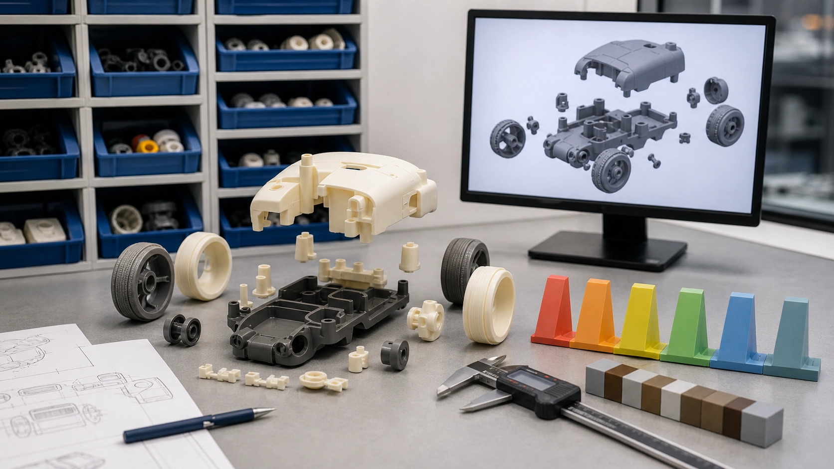
Design for manufacturability, often shortened to DFM, is the practice of adapting a product design so it can be produced consistently with the intended materials, tooling, assembly methods, and quality controls. In plastic toy development, DFM protects the creative idea by addressing physical constraints before they become expensive tool changes or recurring production defects. It does not mean removing every ambitious feature. It means deciding which details matter most and engineering them deliberately.
A useful DFM review begins when the design can still change. Waiting until a final sculpt or appearance model is declared complete limits the available solutions. Early collaboration among product designers, mechanical engineers, tool engineers, decoration specialists, packaging teams, and quality personnel creates more options and makes tradeoffs visible.
Define function before reviewing geometry
Manufacturability cannot be judged without knowing how the toy will be used. The team should define whether it is a display model, an assembled kit, a movable vehicle, a figure, an accessory, or a multi-part play product. Expected motions, removable parts, balance, surface appearance, intended users, packaging orientation, and destination markets influence engineering decisions.
Identify critical-to-quality features at the same time. A face may require clean decoration alignment, a wheel may need a controlled rotation, or a joint may need a particular holding force. Marking these priorities helps engineers protect important design intent when they adjust less critical geometry.
Create a logical part breakdown
A digital concept is often modeled as a single visual object, but injection-molded production may require multiple parts. Part splits can make undercuts releasable, separate colors, hide gates, improve painting access, simplify tool construction, or allow different materials. The best split is not always the fewest parts. A slightly larger part count may produce cleaner surfaces or simpler tooling, while unnecessary fragmentation can increase assembly work and alignment variation.
Each split creates a seam, tolerance relationship, and assembly step. Designers should decide where seams are acceptable and how they relate to natural edges, costume lines, panels, or hidden surfaces. Locating a seam deliberately is usually better than allowing tooling constraints to place it on a focal surface later.
Use appropriate wall thickness and transitions
Consistent wall thickness supports more predictable filling, cooling, and shrinkage. Thick isolated sections can cool differently from surrounding walls and may contribute to sinks, voids, or visible distortion. Very thin sections may be difficult to fill or may feel weak. The appropriate thickness depends on the material, part size, geometry, flow length, and performance needs, so it should be determined through engineering review rather than a universal number.
Where thickness must change, gradual transitions are generally easier to manage than abrupt steps. Ribs, bosses, posts, and internal supports should be proportioned relative to nearby walls. Coring out a heavy area can preserve exterior form while reducing concentrated mass. Mold-flow analysis or sampling may be useful for challenging parts, but simulation results should still be confirmed in the actual tooling process.
Add draft and manage undercuts
Draft allows a molded part to release from the tool. Required draft depends on depth, texture, material, surface expectations, and tool construction. Deep textures typically need more consideration than polished surfaces. Insufficient draft can increase ejection force, create scuffing, or make production less stable.
Undercuts prevent straight tool opening unless they are handled by slides, lifters, inserts, part splits, or flexible release. These solutions can be appropriate, but they add design and maintenance considerations. DFM should distinguish an undercut that protects essential appearance from one that can be simplified without changing the product's character.
Plan parting lines, gates, and ejection marks
Every molded part has evidence of how it was made. Parting lines, gates, vents, ejector locations, and inserts may leave visible traces. Their locations should be reviewed on the three-dimensional model before tooling. A gate on a hidden assembly surface is often easier to manage than one on a decorated focal area, but flow and packing needs also matter.
Engineer joints and moving features
Articulation, wheels, rotating parts, snaps, clips, and removable accessories depend on controlled interfaces. Their performance comes from geometry, material behavior, tolerances, surface finish, assembly force, and production variation. A nominal digital fit with no allowance for variation is unlikely to be a robust production joint.
Engineers should identify which dimensions control motion or retention and define practical limits. Prototype testing can explore the concept, while production-intent samples confirm the actual material and process. Repeated-use expectations, loads, wear, and foreseeable handling should guide the review. Sharp stress concentrations and fragile thin features deserve special attention.
Design decoration with manufacturing in mind
Color and graphics can drive part separation and surface design. Pad printing works best when artwork, pad access, surface curvature, and registration are considered together. Spray painting may require masking edges and holding fixtures. Decals or transfers need suitable surfaces and application access. Highly textured, deeply recessed, or sharply curved regions can make decoration harder to control.
Provide vector artwork, color references, placement dimensions, and a visual tolerance strategy. Small shifts may be noticeable around eyes, panel lines, or boundaries between colors. A decoration sample should be reviewed under agreed lighting and against a controlled reference rather than from screen color alone.
Simplify reliable assembly
Assembly design should make the correct orientation clear and reduce the chance of damage. Features that are easy to distinguish, fixtures that hold parts securely, and joining methods suited to the materials can improve repeatability. If two similar components can be installed in the wrong position, geometry or work instructions should help prevent the error.
Fasteners, welding, adhesives, press fits, and snaps each need enough access and process control. Assembly sequence matters: a decorative surface may be scratched if a later step requires excessive force, or an internal part may become inaccessible after two shells are joined. Walking through the complete sequence before tooling can expose these conflicts.
Include inspection and packaging in the design
A feature is difficult to control if it cannot be measured or compared consistently. Drawings should identify key dimensions, materials, colors, functions, and appearance criteria. Where possible, inspection access and reference points should be considered in the geometry. Fixtures or gauges may be appropriate for repeated functional checks, depending on product risk and the agreed quality plan.
Packaging should support the product without distorting flexible parts, rubbing painted surfaces, or loading delicate projections. Trays, bags, ties, protective films, and carton orientation interact with product geometry. Reviewing a complete packaged sample can reveal risks that are invisible when the toy is evaluated only on a desk.
Control revisions and approvals
DFM decisions lose value if file versions are unclear. Use controlled model names, dated review records, and a consolidated issue list. When a change is approved, record which geometry, color, material, decoration, and packaging version it affects. A production baseline should connect the approved digital files with physical reference samples and inspection criteria.
Conclusion
Good DFM makes an original plastic toy easier to mold, decorate, assemble, inspect, package, and reproduce without losing its intended identity. The strongest results come from early, cross-functional review and controlled decisions. Before authorizing tooling for an OEM project, discuss the part breakdown, material, critical features, finishes, assembly, testing plan, packaging, and destination requirements with a qualified manufacturing engineering team.