
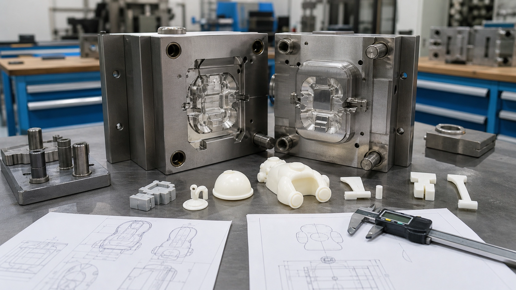
Mold Design Begins With the Product
A reliable mold is the result of coordinated product design, material selection, tooling strategy, and production planning. For a custom plastic toy, the visible sculpt receives much of the attention, but hidden details such as wall transitions, draft, gates, vents, cooling channels, and ejector locations strongly influence the final part. Addressing these features early can reduce avoidable redesign after tooling begins.
Mold decisions are specific to the geometry, resin, finish, expected production conditions, and quality requirements. General guidelines are useful starting points, not universal dimensions. The product designer, mold designer, molding engineer, and assembly team should review the same current model and specification before steel is cut.
Define Parting Lines and Mold Direction
Choosing the Opening Direction
The mold must open so the part can release without damage. Establishing the primary opening direction reveals which surfaces need draft and which features create undercuts. For sculpted toys, the direction also determines where the parting line appears. A line across a face or a highly visible decorative area may be harder to finish consistently than one placed along a natural edge, seam, costume boundary, or less visible surface.
Managing Undercuts
Hooks, recessed details, side holes, and some joint features may prevent straight ejection. Slides, lifters, collapsible features, or separate components can resolve an undercut, but they add tooling movement and maintenance considerations. Sometimes a small product-design change removes the undercut without affecting the appearance. The team should compare function, visible seams, assembly work, and tool complexity before selecting a solution.
Control Walls, Ribs, and Structural Features
Wall Thickness and Transitions
Relatively consistent walls promote more uniform filling and cooling. Heavy local sections can cool slowly and may contribute to sink marks, internal voids, or distortion, while very thin areas may be difficult to fill. When thickness must change, gradual transitions are generally easier to mold than abrupt steps. The appropriate dimensions depend on the resin, flow length, surface requirement, and part geometry.
Ribs and Bosses
Ribs can stiffen shells without making an entire wall heavier. Bosses can locate screws, pins, axles, or mating components. Both features need careful proportioning and support because a thick rib or boss can mark the opposite cosmetic surface. Fillets may reduce sharp stress concentrations and help material flow, while adequate spacing can improve cooling and tool strength.
Draft for Clean Release
Draft is a slight taper that helps the molded part leave the core and cavity. Textured surfaces and deep features often need more release allowance than shallow polished surfaces. Insufficient draft can cause scuffing, drag marks, deformation, or unstable ejection. Draft should be evaluated after the texture and parting strategy are known, because a late texture decision can change release requirements.
Plan Material Flow Through Gates and Runners
Gate Location
The gate is where molten plastic enters the cavity. Its location influences fill pattern, weld lines, air traps, orientation, packing, and the visible gate vestige. A hidden gate is not automatically the best choice if it creates poor flow through a critical thin feature. Mold-flow analysis and practical tooling experience can help compare locations, but trial results should still be evaluated on production-intent parts.
Runners and Balanced Filling
In a multi-cavity or family mold, the runner system should support stable filling of each cavity or component. Parts with different volumes or flow resistance may not fill identically from a simple shared layout. Runner dimensions, gate sizes, and process settings are developed as a system. Hot-runner and cold-runner approaches each have product, material, maintenance, and cost implications that should be reviewed for the project.
Venting Trapped Air
Air needs a controlled escape path as the cavity fills. Poor venting can contribute to burns, incomplete details, or inconsistent filling. Vents may be placed near the end of fill, along parting surfaces, or through suitable tooling features. They must release gas without allowing unacceptable flash and should be accessible for cleaning where practical.
Design Cooling and Ejection Together
Cooling for Dimensional Stability
Cooling layout affects cycle consistency, shrinkage, warpage, and surface appearance. Channels should remove heat as evenly as the tool construction allows, especially around thick regions, cores, and changing geometry. Local hot spots can cause one area to remain soft while another is ready to eject. Cooling design must also leave enough steel around cavity details, fasteners, and moving mechanisms.
Ejecting Without Visible Damage
Ejector pins, sleeves, plates, or other mechanisms apply force to release the part. Their positions should support the part without creating severe marks or distortion. Cosmetic areas are normally avoided when suitable alternatives exist, but hidden locations still need enough strength. Deep shells may hold the core through vacuum or shrinkage, so release, polish direction, draft, and ejection area must work together.
Protect Surface Detail and Assembly Fit
Texture, polish, paint masks, pad-print areas, and molded graphics should be considered during tool review. Very fine sculpted detail must be manufacturable in both the cavity and the finished plastic. Sharp internal corners can be difficult to machine or fill, while texture can soften tiny features. Agree on reference samples and inspection lighting so subjective appearance decisions have a shared basis.
Assemblies also need realistic tolerances. Snap fits, rotating joints, pins, sockets, screws, and glued seams respond differently to material shrinkage and process variation. Nominal CAD alignment is not enough; the design should allow for dimensional ranges and the intended assembly method. Components molded in different materials or colors may require separate tolerance reviews.
Use a Structured Tool Review
- Confirm the latest part revision, resin, shrinkage assumption, and cosmetic classification.
- Review mold direction, parting lines, shutoffs, undercuts, slides, and insert strategy.
- Check draft, wall transitions, ribs, bosses, radii, and likely sink-sensitive areas.
- Review gates, runners, vents, weld-line expectations, and gate-removal method.
- Review cooling, ejection, cavity identification, replaceable details, and maintenance access.
- Confirm critical dimensions, assembly interfaces, finish references, and trial acceptance criteria.
Conclusion
Good plastic toy mold design balances visual intent with repeatable molding, clean release, practical assembly, and maintainable tooling. Early cross-functional review is more effective than treating the mold as a copy of the final CAD model. To prepare an OEM project, share complete geometry, material targets, finishes, assembly needs, and critical quality points with an experienced manufacturing partner.